IEC 60071-1 [3.15] defines earth-fault factor k to be
at a given location of a three-phase system and for a given system configuration, the ratio of the highest r.m.s phase-to-earth power-frequency voltage on a healthy phase during a fault to earth affecting one or more phases at any point on the system to the r.m.s value of phase-to-earth power-frequency voltage which would be obtained at the given location in the absence of any such fault
Selection of the appropriate power-frequency withstand level is related to the earth fault factor for the system. Earth-fault factor is used to determine the highest voltage an electrical equipment can withstand during overvoltages such as lightning or switching surges.
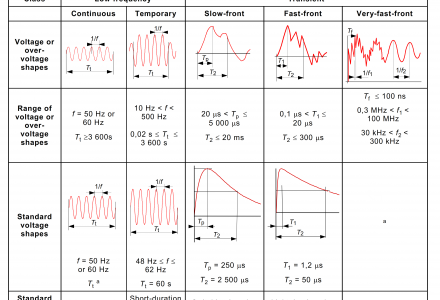
IEC 60071-1 [3.17]classify of voltages and overvoltages according to their shape and duration, voltages and overvoltages are divided in the following classes
The earth fault factor can be calculated from the symmetrical component parameters of the system R0 , X0 , and X1 , where:
R0 is the zero phase sequence resistance
X0 is the zero phase sequence reactance
X1 is the positive phase sequence reactance
- For a solidly earthed system for which
 and
and  the earth fault factor will not exceed 1.4.
 - For a non-effectively earthed system for which
 and
and  the earth fault factor will be
  or 1.7.
 - For a system earthed via an arc suppression coil the earth fault factor will be 1.9
The higher the earth fault factor, the higher should be the rated power-frequency one minute withstand voltage. Lightning impulse withstand voltage is tied to power-frequency withstand voltage so that once the latter has been determined the former is automatically fixed.
References:
- IEC 60071-2011 Insulation co-ordination
- The J & P Transformer Book, 12th Ed.
