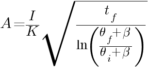
The sizes of earth conductors and earth electrodes are almost always chosen from typical sizes as provided by a particular project standard. If using non-typical sizes can extensively impact the cost of the project, it would be best for the Electrical Engineer to calculate the required sizes of earth conductors and earth electrodes.
IEC 60949:1988 – Calculation of thermally permissible short-circuit currents, taking into account non-adiabatic heating effects provides a formula in calculating the cross-section of the earthing conductor or earth electrode when the fault current is interrupted in less than 5 s.

where:
 – cross-section in mm²
 – conductor current in amperes (RMS value)
 – duration of the fault current in seconds
 – constant depending on the material of the current-carrying component; Table 1 provides values for the most common materials assuming an initial temperature of 20 °C
 – reciprocal of the temperature coefficient of resistance of the current-carrying component at 0°C (see Table 1)
 – initial temperature in degrees Celsius. Values may be taken from IEC 60287-3-1. If no value is laid down in the national tables, 20 °C as ambient ground temperature at a depth of 1 m should be adopted.
 – final temperature in degrees Celsius
| Material |  in °C in °C |
K in  |
|---|---|---|
| Copper | 234.5 | 226 |
| Aluminium | 228 | 148 |
| Steel | 208 | 78 |
